
Wiring Your Camper Van Electrical System – Practical Guide
You’ve calculated your solar. Planned your build. Bought some components and made sure it’ll all fit. Now, how does go together?
In this article we’ll tell you how to find the wire sizes, fuse sizes and other parts needed to build your camper van solar system.
To see complete wiring diagrams for RV solar panel systems click here.
Electricity is a serious task to take on. There are many examples of things online that “can” be done but should not, so consume Youtube instructions and articles (even this one) with caution. If in doubt, stop and ask an expert.
A tip before you begin: If you are new to electricity, then there’s a good chance you’ll make mistakes. It’s much safer and cheaper if those mistakes are on paper (or screen).
We find it helpful to draw out what you plan on doing and asking experts on an electrical forum if your plan is correct. Even if you’re experienced it’s not a bad idea to have some more eyes on things. Solarpaneltalk.com and Northern Arizona Wind and Sun forums are full of helpful folks. And now, the warning:
Start With Wire Size
Electricity has to be able to fit in the metal wires you install. Trying to pull too much current through them can reduce their efficiency and even make them burn up.
Wire thickness is determined by
- Wire length
- The amount of Amps passing through it
Wire diameter is commonly measured in AWG, or American Wire Gauge, increments. The smaller the gauge, the larger the diameter of the wire. A 16 AWG wire is tiny compared to a 4 AWG wire.
Below is a chart for picking your minimum wire size. To use the chart:
- Figure out how many amps will pass through the wire.
- Figure out about how far away the component will be from the battery. The length of your circuit is the total length, meaning double the distance between component and battery.
- Choose a wire that can handle the amps with a little buffer (25% or so).
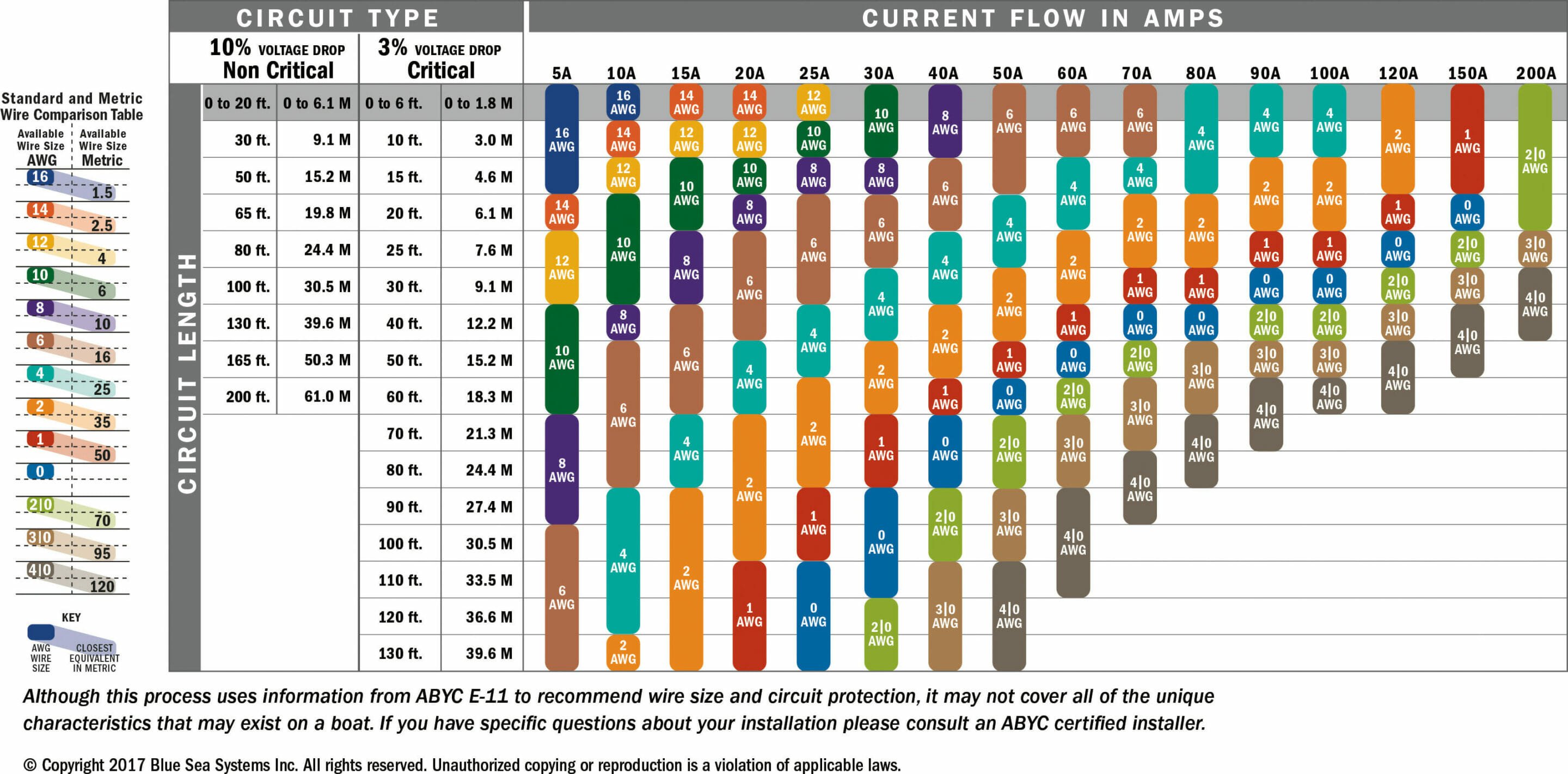
Example: if you have a set of lights that draws 4 Amps and is 7 feet away from your battery: 4A x 1.25 buffer factor= 5A. Go to the 5A column. 7ft x 2 positive and negative circuit= 14ft. Go to the 15ft row. You find that 16AWG is the minimum wire size.
Quick Tip: There is no major downside to getting wire that is larger than required. For most components in a van other than the inverter, 12AWG wire is plenty. It’s easiest to buy a large red and black roll of 12AWG to use for all of the small items such as fans, fridges, and lights. No need to get several different wire sizes and have excess strands and work with tiny wires.
Buy multi stranded wire as it is easier to route and better able to handle the vibrations of a car. Don’t use solid copper household wiring (known as Romex).
Fusing
A fuse’s primary purpose is to protect the wiring. Most of the rules for fuses derive from this.
- Never install a fuse that is larger than the current rating for the wire. Smaller is fine. Use the same wire chart above above for your maximum fuse size.
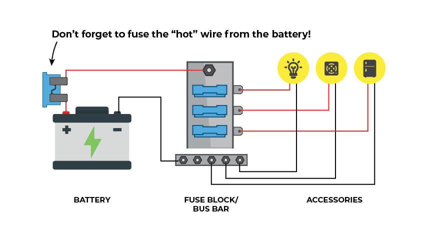
- Install the fuse as close to the battery (or “hot” end) as possible. This way if the fuse operates, there will be less wire that can still carry power.
- Fuse all circuits that can have power running through them. A circuit is the full (+) to component to (-) loop. No fuse is needed on the (-) return wire for this type of system.
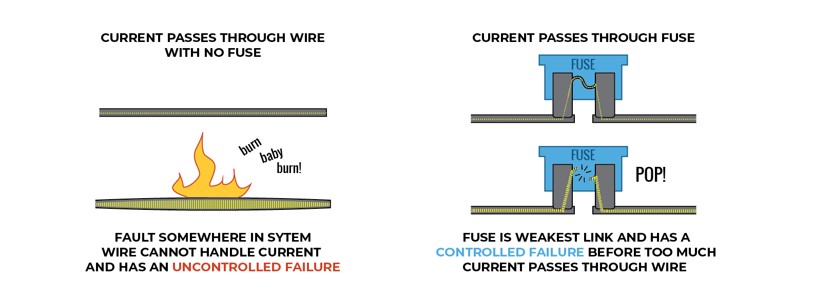
Fuses come in all shapes and sizes, but functionally they all work the same way. They have a small element in them that will break at as calculated number of amps passes through:
Some people install breakers in a van instead of fuses. Breakers are helpful in a house when large circuits need to be turned off for repairs. Because breakers are slow to blow, they also help for electronics that can have a quick spike in electricity, such as when a clothes dryer kicks on. We don’t find them particularly useful in a van because this same feature that allows for a spike in electricity can allow that spike to damage your electrical components.
Fuse Blocks and Bus Bars:
To organize power running from your batteries to all of your small electronic accessories you use a fuse block. This way you don’t have to manage a bunch of dangling wires.
A bus bar is essentially a piece of metal to attach all of your return (-) wires to. Many fuse blocks have them built in. This is cleaner for circuits as the power is all passing to the battery at the same point.
Recommended Fuse Blocks and Bus Bars
Using the vehicle chassis (or not!)
Almost all vehicles on the road have a chassis ground. What this means is that the (-) post on the vehicle battery is connected to metal on the frame, motor, etc. as part of the electrical system. This also means that in vehicle wiring you can feasibly just attach the (-) wire on your components to the metal frame instead of running a long wire back to the bus bar. In theory, you can do this with your van electrical system as well.
This practice is tempting but discouraged for several reasons, especially on newer vehicles:
- Galvanic corrosion. When two different types of metal are touching with electricity passing through them they can corrode. Older vehicles were build using all steel parts bolted together, but newer ones mix in aluminum and other metals and you don’t want electricity passing through.
- Vehicle construction. Many newer vehicles use rubber and plastic pieces to reduce vibration. Because of this, there are less metal surfaces touching between the cab of a van and the battery. Not great for electrical current to pass through.
- Feedback loops. If you have several different lengths of routes of electricity with different resistances they can create feedback loops that can mess with some electronics in your vehicle (and audio equipment).
- It’s easy to avoid. Just running a pair of wires instead of one isn’t much more effort or money as long as you plan for it.
Caveat: you should still ground your battery as well as any metal ground terminals on your electrical parts! You don’t want a full floating system as that gets more complicated. Most big items such as inverters and refrigerators have a (+), and (-) and a ground terminal. The ground terminal is usually just a metal thread with a nut on it and should be attached with a wire to metal on your frame. “Grounding” your metal components to the chassis is important and we rarely see it properly done in DIY van builds.
Planning your wire routes:
For all of your 12V systems you want as short of a wire as possible. This is even more true for your high current parts to stay efficient. You want your batteries close to your charge controller, which should be close to your inverter, etc.
We like putting in wiring on top of insulation and flooring so that you don’t have to dig up too many things if it goes wrong. For the ceiling you might run wires above paneling for the lights. For the major planners out there, we’ve seen people run PVC pipes through the walls to be able to add or troubleshoot wires!
Tip: If you’re running wires behind walls you can use a puller string to aide you. Before you put your walls up, lay a piece of string where your wire route will be. Then, when you’re ready to run wires through, tie the string to the wire and pull it through! Each time you do this, pull another piece of string along with your wire so that you always are able to pull another wire should you need it.
Any wiring coming from your inverter can be quite long without any efficiency loss, so put it close to your battery with extensions coming from it.
Terminals and Crimping
Above is a quick video on how to crimp terminals to wires. A basic stripper and crimper is OK for this kind of project.
For any wire thicker than 8 AWG it’s recommended to buy wire with terminals pre-installed or have them installed at a battery store. It takes an additional special crimper tool to apply enough pressure to attach larger terminals.
Make sure to use a connector that is appropriate for the wire size. They are usually labeled.
When attaching cables to your battery or frame, you want the electricity to flow through as few of surfaces as possible. This means that you don’t want to sandwich any washers between the connecting surfaces (but above them is fine).
How to wire solar panels in order:
- When wiring solar panels, always connect the panels to the system at the very end and disconnect them first. You don’t want that voltage connected to a charge controller with nowhere to go.
- After the above tip, it’s a good habit to disconnect the negative (black) battery terminal before working on electrical systems.
The order of assembly should be:
- Connect all system wires
- Connect negative battery terminal
- Connect solar panels to charge controller
- Disassembly is in reverse of this
Additional tips
- Get a Digital Multi Meter (DMM). This is critical for anyone doing electrical work as well as troubleshooting many electrical issues. For basic wiring you don’t to spend more than $20 like this Craftsman DMM to get the job done.
- Use dielectric grease on your connections. This is used to keep bare metal connections from corroding. Vaseline works for this as well if you already have some.
- Get a variety of fuse sizes here
- Wiring is the cheapest if you buy directly from a hardware store so that is what we recommend
I am new to solar and van living. I purchased a renogy 200 watt kit which came with the pwm wanderer charge controller. I bought a 12 volt fullriver agm 100 ah battery. At the purchase the attendant said the battery was at full charge brand new out of the box. I hooked everything up to a 400 watt inverter which has a meter on it. when in charge mode it reads 13.1 volts…i’m assuming this is good? When I use my dvd player and tv at night the voltage drops down to 12.5 and I shut off tv when it drops to 12.3 as I believe this is 50 percent drainage on the battery. I”m not sure why the voltage drops so drastically and why on websites it says a fully charged battery can be as high as 14 volts on the meter. Do I have a bad battery?
Everything works fine…I followed your 200 watt plan to the T.
Any suggestions?
Thanks,
Eric
Eric:
You’re learning that lead acid batteries are tricky at best to judge. I’ll start off by saying that everything looks normal to me. Keep in mind, I’m not an electrician, but I do have some experience that should help you out:
1) A normal 12V battery reads at 12.7-12.8V when full. What does “full” mean? It means the battery has been charged all the way and then has sat -with no loads on it- for half a day. This “equalizes” the cells and lets the charge balance.
2) Similar, a battery at 50% drain will read at about 12.1V. Again, this is after the battery has sat for half a day. In reality, neither of these values are easy to come by in a van because you’re usually always charging or draining, so you can use these numbers as reference but not hard values.
To charge a battery to full, you need to put more voltage in it than it’s currently at. The higher the voltage, the faster it will charge- but too high of voltage and it will burn/explode/etc. Lead acid can be charged at up to 14.4V or so (sometimes higher). Your charge controller will try to put this much voltage into it if it can, but if your battery is fairly low the CC might have enough power to get up that high. It might only read at 13.1V like you’re seeing. It’s still charging the battery, and once your battery gets full enough this reading will get higher. The charge voltage relates to how much solar power you’re getting and how drained your batteries are so it’s not a hard number. But this is just the charging voltage- it’s not directly related to how full your battery is other than in optimum conditions (good battery/charger ratio, etc), it will get into the 14V range. But anything over 13V and your battery is charging.
Now to understand what I like to think of as “momentum” in the system. If your batteries are charging at 13.1V, and you take the charger off, the batteries might drop but still read at 12.9V. Even with nothing on them, the internal cell voltage is still higher from charging and will take an hour or two to settle to 12.7V or 12.6V or however high it is. Same with if you’re draining the batteries fast. You might plug a laptop in and see it drop to 12.1V or 12.0V and when you take the laptop off and let the batteries sit, they’ll recover a bit from the discharge voltage and sit at 12.2V after an hour or two. This is the bit that’s confusing because you can have a battery that’s 95% charged read at 12.9V due to the momentum, when technically a 100% charged battery will read at 12.7V.
So- what does this mean in real life? Your batteries are charging at anything over 13.V. Higher is better, and 14V+ is great so don’t be worried if you see those numbers. If you’re charging from a deep discharge this might take a few hours to get up there- and you might never see that number unless you’re in the southwest with 12 hours of sun. Same with discharging. Shut everything off if your batteries get below 12.0V, as this means you’re probably below the 50% mark. You can go lower once or twice if you need to, but it’s good to avoid. Hope this helps shed some light on the situation!
One last metaphor to help out: Think about Voltage as Pressure. If I have a battery at 12.5 PSI, then I need to put more than 12.5 PSI into a pipe to fill that battery. The higher the PSI, the faster the battery will fill. Putting 13.5 PSI into a pipe will fill it faster than 12.7 PSI. After about 14.4 PSI, the battery has too much pressure and can explode. Your CC has a pump that can reach up to 14.4 PSI, but if your battery is huge or sitting really low, then the pump will not be able to get up to that pressure because it has too much battery to fill.
Howdy there, thanks for all the articles and your time in doing them! Most of the electrical articles all have solar built in. Say I don’t want to do solar. In the diagram, can I just “cut out” the top 2 green sections and effectively just start with the batteries down? Thanks!
Dylan
Thanks for the interesting article about the wiring in a campervan. You mentioned it’s important to not install a fuse larger than the current rating. It seems important to take notes of what the current rating is, especially so you know what fuses you will need.
Taylor, a bit of clarification: The maximum fuse size is determined by the current rating of the wire (as seen in the chart at the beginning of the article). You can determine the max fuse size without even knowing what devices you will be connecting simply by the wire size. With that said, I will often “downsize” a fuse on a circuit that isn’t using much power. If I have lights that are drawing 2.5A and a wire rated at 15A, then I’ll usually use something like a 5A fuse. Just nothing above 15A.
when or if I should use a fuse on the negative terminal as well as the Positive?
Hello, we have 520watts of solar connected to 6 100amp hour sealed AGM batteries. During the day when the sun is out the solar charger and inverter read 13.7-13.9v my inverter and charge controller read at around 12.7v as soon as the sun goes down. When we test them with a multimeter it reads about 12.9, the batteries are wired in parallel and we unwired them and tested again and they read between 12.85-12.95 is this normal? Before we tested with the multimeter we thought we had one faulty battery that was throwing it off the reading hence the 12.6-12.7v but after we tested individually, they all were reading above 12.85v but the inverter reads at 12.6-12.7v. Is there another issue that we’re not considering or is it normal for inverters and charge controllers to read lower that what your batteries actually are?
Kaoutar:
Its possible that you do have some variance in you electronics voltage meters. This isn’t unheard of, but it’s more likely that you have undersized wiring or poor connections somewhere in your system. If your wiring runs are long or your wire is small, you might experience a voltage drop. The quick way to test this is to use your Multimeter and read the voltage at the connections for your CC and your inverter (rather than at your batteries). If the voltage reads at 12.7V going in, then you have a voltage drop and you want to go through and make sure you connections are all clean (even put some dielectric grease or vaseline on them) or upsize your wiring. If the voltage going into your CC/inverter reads 12.9V, then you just have a bit of variance and have nothing to worry about.
Hello, I am in the middle of my van build and your website has been the most helpful information I have come across! I just have a question regarding gauge size…I was told by the company who sells my fan I can use 14 or 12 gauge wires…I only need to wire the fan, led lights, electric water pump, and refrigerator…I went ahead and got 14 gauge wires…do you think this will be sufficient for everything I’m powering, or should I go with the 12 gauge as you suggested. Thanks so much!
Michelle-
Short answer: you’re probably just fine with 14AWG. Long answer: I can’t be certain without knowing the specifics of your setup. The wire size is determined entirely by the draw of your specific appliances as well as their distance from the battery. Most sink pumps draw about 1.5A or less- this shouldn’t be an issue at all for 14AWG (if you look at the chart above). A 45L fridge usually draws about 5A. If you look at the chart above, that limits you to a 20ft circuit for 14AWG (which is 10 ft each way). So as long as your wires are 10ft or less to your fridge, then you’ll be OK with 14AWG. If you have a fridge that draws more power or is further away, then you’ll want 12AWG. Check out the tech specs of your fridge to know for sure.
With the fan, again it’s hard to tell. The Fantastic fans Usually draw less than 3 amps. 14AWG would be fine for this. The Maxxfan uses up to 5A on full speed, which is fine if the wires are 10ft long or less. If it’s further away from your battery, then I personally would use 12AWG wire.
Hope that gives you enough to go off of!
When you say that you rarely see properly grounded wires, what do you mean? What does a properly grounded wire look like and what is the purpose?
Thanks!!
Nice work on all the info. So I have 2x 12v 125ah batteries in parallel going to a bus bar which then goes out to inverter/solar controller / alternator charger / DC fuse panel. It’s a 1000w inverter and max amp draw from DC circuit will be 35amps. What wire would you recommend awg between batteries and bus bar with which fuse? Also what wire size from bus bar to inverter and fuse?
Hey Guys,
I was wondering what you think the best way of stepping the 12V from the battery down to 5V is? For a USB charging a phone for example? Thanks a bunch!
Kevin
Hi- Great article. Thank you! I’m hoping you can help me. I have a mini motorhome that came without an auxiliary battery for the coach. In the compartment there are half a dozen wires with lugs. No bus bar. How can I figure out what wires go to what terminals on the battery? Two have inline fuses; I’m pretty sure they go to the positive terminal. But “pretty sure” in relation to working with electrical components is the same as “I have no idea”. Is there a way to use a digital multimeter and the new battery to tell which wires go where? -Thanx, OregonSteve
I have learned a lot form your site I am building a camper out of a 5×8 inclosed trailer I am running 16 awg 12 volt wire for the 12 volt items, there will be 8 led lights not all on at the same time and a separate 16/3 romex wire for 1 110 TV outlet. for now I will be charging my 100 Ah battery at home. with a battery charger maintainer then down the road put solar in. My long winded question is this, will I be ok with 16 awg wire for the 12 volt lights and using a 1500 watt inverter for the 110 outlet that will be 5 feet from battery to outlet.
HI I BOUGHT A KEYLINE BRAND SMART BATTERY ISOLATOR TO INSTALL IN MY VAN. I ALSO BOUGHT 2 150AMP FUSES TO SPLICE INTO THE POSITIVE CHARGE CABLES AS WAS RECOMMENDED ON ONE OF THE VAN BUILD WEBSITES. SINCE MY VAN WAS FORMERLY A WHEELCHAIR VAN COMPLETE WITH AN ELECTRIC LIFT (SINCE REMOVED) THERE IS ALREADY A 90-AMP CIRCUIT BREAKER THAT IS MOUNTED VERY TIDILY UNDER THE HOOD WIRED TO THE STARTER BATTERY CIRCUIT. WILL A 90-AMP CIRCUIT BREAKER SUFFICE INSTEAD OF A 150A FUSE FOR THIS PURPOSE, OR IS IT ABSOLUTELY NECESSARY THAT I REMOVE IT AND REPLACE WITH A 150A FUSE. IN EITHER CASE I DO PLAN ON INSTALLING A 150A FUSE ON THE LIESURE BATTERY SIDE OF THE SYSTEM. THANK YOU
I found your article very informative. I will make certain to bookmark your blog and will often come back from now on. I want to encourage continue your great job